CAD files deliver highly accurate 3D assets perfect for precise visualizations. However, they often include unnecessary internal geometry (such as product internals or assembly components) that won't be visible in marketing renders, real-time applications, or web-based 3D viewers. InstaLOD's Occlusion Cull operation automatically detects and removes these hidden interior elements, dramatically reducing file size while boosting performance.
Like all of InstaLOD’s mesh operations, Occlusion Culling is a scalable operation that can be performed on large data sets without adjusting any of its settings. This article explores key features and workflows that leverage InstaLOD's Occlusion Culling technology, establishing it as a critical tool in any CAD-to-3D processing pipeline.
To learn more about the individual parameters and functions of the operaiton, please read our dedicated article on the Occlusion Cull mesh operation.
¶ Automatically Remove Hidden Polygons
Removing hidden geometry with InstaLOD is straightforward: import your CAD data and run the Occlusion Cull operation. Let's look at an example. Here we have model of an engine that comes from CAD data. If we hide some of the external parts of the model, we can see a significant amount of the model contains polygons inside the engine. Since we won't be creating an exploded view illustration, all of this internal geometry is unnecessary.
Let’s remove all of the polygons on the inside of the engine with the Occlusion Cull operation’s By Polygon culling strategy. This will tell InstaLOD to remove individual polygons that are occluded giving it a fine level of control over what gets removed.
Create a new profile, or if you have a profile already, add a new mesh operation and select Occlusion Cull at the top of the Mesh Operation Settings panel. In the Occlusion Cull Settings section, change the Culling Strategy to By Polygon.
In this example, we'll set the Resolution to 512 and the Adjacency Depth to 3. Higher resolution values produce more accurate occlusion culling but require more processing time. Start with the default and adjust as needed.
To run the operation, click Start in the Mesh Operations panel on the left. The video below shows the occlusion culling results by hiding the external pieces again. Most of the interior geometry has been removed, with carefully placed pieces still visible through the holes in the front and back of the engine. This process would normally take hours to determine which parts are visible and which are safe to remove. With InstaLOD, it takes seconds. We've significantly reduced the polygon count while maintaining the exterior quality since we only removed the polygons we didn't need.
¶ Adjacency Depth
The Adjacency Depth parameter determines how many adjacent faces around visible polygons are retained during removal. A value of 3, for instance, keeps up to 3 layers of neighboring hidden faces surrounding each visible polygon, which lowers the possibility of gaps in densely tessellated meshes. Increasing this value allows you to reduce the Resolution parameter for faster processing times if needed.
¶ Optimizing the Rest
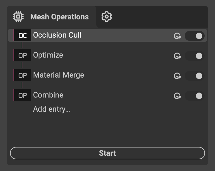 After removing occluded geometry, continue optimizing your asset with other InstaLOD mesh operations. Use the Optimize operation to further reduce the polygon count in the remaining geometry. Apply the Material Merge operation to consolidate materials in the scene. Then use the Mesh Toolkit to combine objects and reduce draw calls. InstaLOD's mesh operations work together to create a complete end-to-end workflow that scales across entire asset libraries and data sets.
¶ Transparent Objects
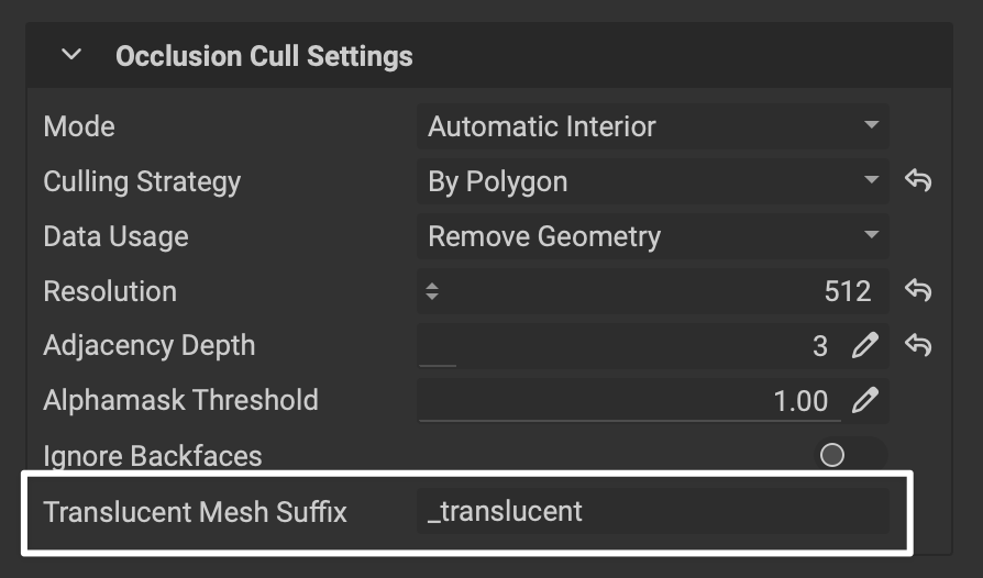 When processing a scene with transparent parts (such as car windows), use the
 Translucent Mesh Suffix setting to inform InstaLOD of which submeshes are transparent.
¶ Camera-Based Mode
Camera-Based Occlusion Culling removes geometry that isn't visible from specific camera angles, making it ideal for fixed-perspective applications like product configurators or architectural walkthroughs. Simply position cameras in your scene where viewers will see the model, and InstaLOD will remove any geometry not visible from those viewpoints. This approach is particularly useful when you know exactly how users will interact with your 3D content.
To use the camera-based mode, in the Mesh Operation Settings panel on the left under Occlusion Cull Settings, change the Mode to Camera Based.
¶ Writing Optimizer Weights
InstaLOD's Occlusion Cull operation can write optimizer weights that tell the Optimize operation which areas to simplify more aggressively. When enabled, occluded areas receive weights that allow the polygon optimizer to more aggressively reduce polygons in hidden regions while preserving detail in visible areas. This creates a two-stage workflow that intelligently balances polygon reduction across your entire model. This is particularly useful when you need to preserve specific interior submeshes and their attributes (such as material assignments and UVs) while still reducing an asset’s polygon count.
For example, consider a car interior with detailed dashboard components, seats, and door panels. By running Occlusion Cull with optimizer weight writing enabled, InstaLOD assigns reduced weights to areas like the underside of seats or hidden mechanical components beneath the dashboard. When you subsequently run the Optimize operation, these weighted regions are simplified more aggressively, while visible surfaces like the steering wheel and instrument cluster retain their detail. This approach delivers significant polygon reduction without compromising the visual quality of what viewers actually see.
To use the Occlusion Cull operation to write optimizer weights:
- In the
Mesh Operation Settingspanel on the right, underOcclusion Cull Settings, change theData Usagedropdown toWrite As Optimizer Weights. This writes vertex colors into the mesh that the polygon optimizer reads during processing. - Add a new Optimize mesh operation to the InstaLOD profile.
- In the
Mesh Operation Settingspanel, underAdvanced, change theOptimizer Weightsdropdown toColor Set Index. This defaults to color set index 0, where the Occlusion Cull operation writes the weights. - In the
Profile Settingspanel on the left, enablePrevious Output As Inputto pass the occlusion culling output directly to the optimize operation.
With this two-stage workflow, InstaLOD can process any input mesh by detecting occluded geometry and applying more aggressive optimization to hidden areas while preserving detail in visible regions.
¶ When Should I Use Occlusion Culling vs. Remeshing?
Both Remesh and Occlusion Cull operations remove internal or hidden geometry. When should you use one over the other?
¶ Occlusion Cull
Use Occlusion Cull when you need to preserve the original mesh structure, materials, and UV coordinates while removing only the hidden polygons. This operation is ideal for CAD data where maintaining the exact geometry and material assignments of visible surfaces is critical.
Follow up with the Optimize, Material Merge, and Mesh Toolkit operations to further reduce polygon count, consolidate materials, and minimize draw calls.
¶ Remesh
Choose Remesh when you need a result with completely new topology optimized for real-time rendering. It generates a clean, optimized mesh from scratch with efficient UVs and merged materials, though it doesn't preserve the original UVs or material assignments from the source mesh. Remeshing also combines submeshes together into a unified result parts overlap or intesect.
Learn more about the remeshing kitbash workflow in our dedicated article.