The tessellation of CAD data is typically processed on a global scale, meaning that entire assemblies are tessellated using the same settings. In many cases, this is not sufficient, as different parts often need different tessellation quality settings. With InstaLOD, CAD files can be tessellated on a per-part level with a wide range of control.
¶ Importing CAD Data
To import a CAD file, drag/drop the file into the viewport or use Open Scene in the File tab.
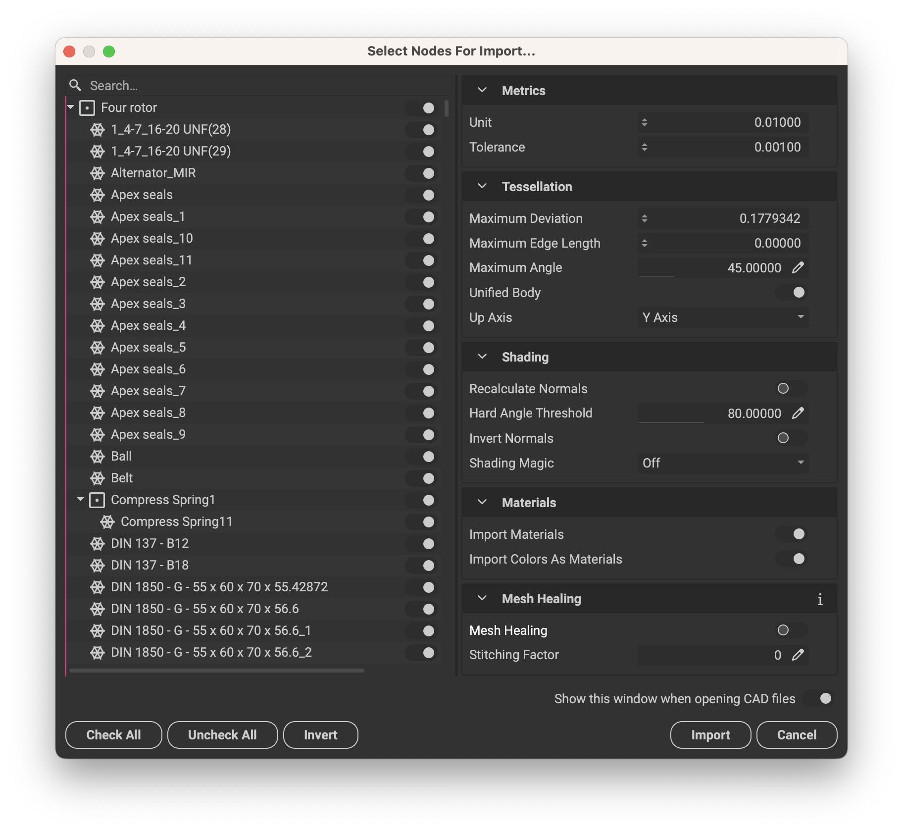
When a CAD file is loaded, an import window appears where users can choose which parts or sub-assemblies to import. The global tessellation can be specified using the Tessellation Settings with additional control over the Up Axis orientation (X-up/Y-up/Z-up).

After the initial tessellation, files can retrospectively be readjusted using the CAD Live Link. Shading issues, such as splits, can be fixed using the Shading Settings.
To always import the whole assembly with default tessellation settings, simply disable Show this window when opening CAD files. This setting can be re-enabled under Preferences-> Application.
¶ Tessellation Settings
- The
Maximum Deviationtessellates using a deviation in units from the original CAD surface - The
Maximum Edge Lengthsets the maximum length of edges created when tessellating - The
Maximum Anglesubdivides areas that exceed the allowed angle between two polygons, to stay within the specified threshold.
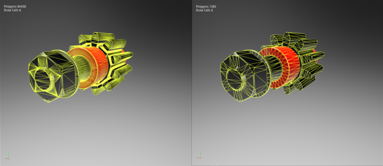
The Maximum Angle can give good tessellation results, however, it oftentimes generates dense geometry when tessellating small parts within larger assemblies. This occurs due to the strong curvature of small parts, which could potentially generate +50k polygons for a single screw.
85k Poly 7k Poly

Therefore, the Maximum Deviation can be used to ensure that the model stays within a specified threshold of quality, without generating unnecessary subdivisions.
¶ Shading Settings
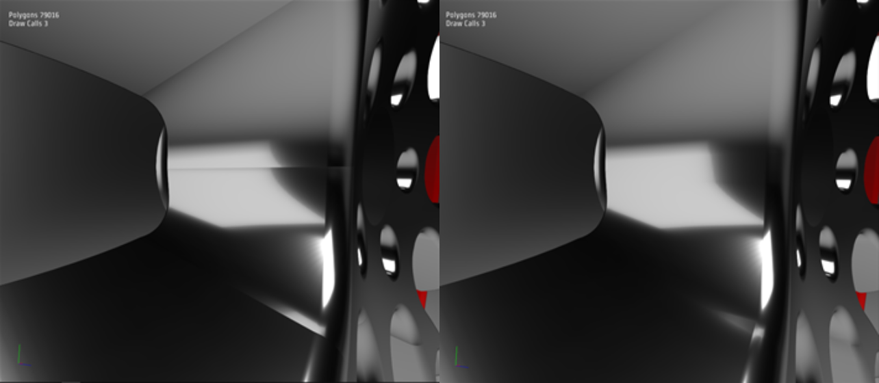
The Shading Settings allow users to selectively, (or automatically) fix shading issues on CAD models. In the example displayed below, various shading splits (Fig. 1) are scattered around the model that, in this case, occur due to incorrect normal positioning. This is typically a manual task to fix, which can become a tedious and time-consuming process. With InstaLOD Studio, shading issues like these can be fixed in an automated fashion.

Fig. 1 (Left) and Fig. 2 (Right)

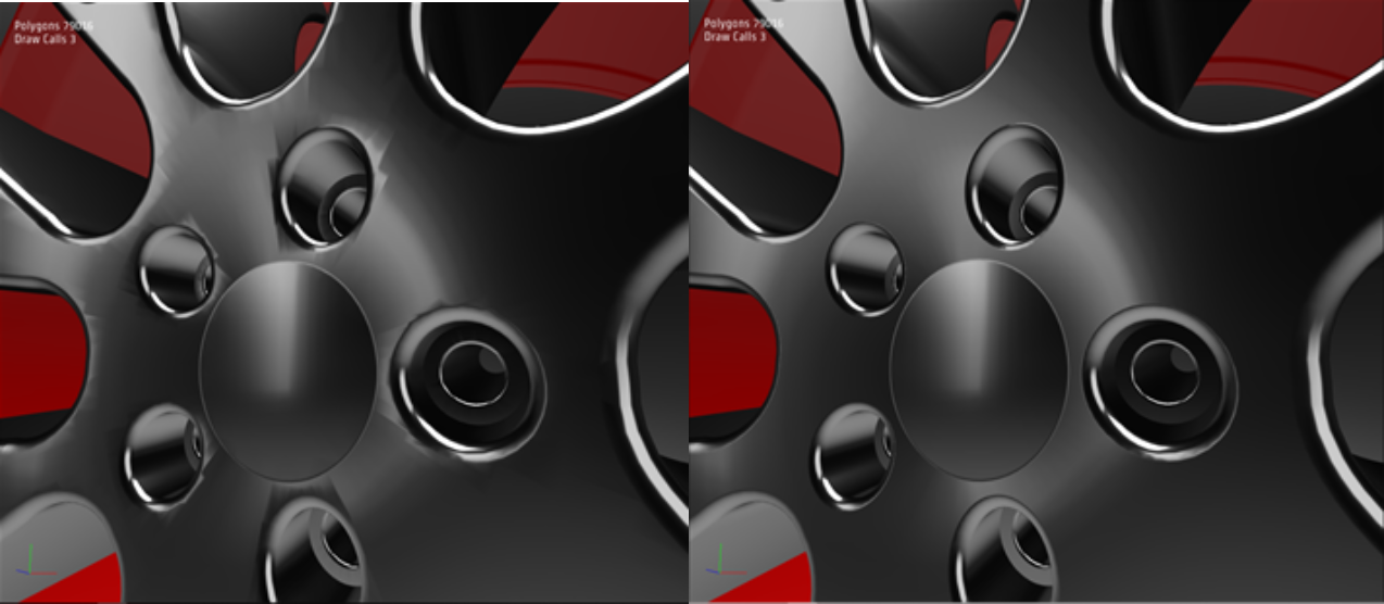
Fig. 3 (Left) and Fig. 4 (Right)
To fix these kinds of splits, Recalculate Normals can be used, which in this specific case doesn’t give the desired result due to it creating singularities (Fig. 3). To fix these splits correctly without creating singularities, Shading Magic needs to be applied. Shading Magic looks at the original CAD file’s NURBS curves and surfaces and figures out where to fix problematic areas.
This gives the desired result without creating any new shading issues (Fig. 4).
In some cases, it can be desirable to maintain specific splits but remove others. In that case, the Manual Adjustments can be used to fix shading selectively by applying vertex paint to only the vertices where shading fixes are desired. For more information on vertex painting, please read vertex painting.